You can assign tool defaults to walls, surfaces, lines, dimensions, text and photos using the Tool Defaults option of the Edit menu. These defaults will be used whenever you add walls, surfaces, lines, dimensions, text and photos to a plan. Any changes you make to defaults will remain until you close the Icovia window.
To Assign Tool Defaults:
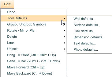
| 2. | A sub-menu with all the tools available for setting defaults will be displayed to the right. Select the tool for which you want to set the defaults by clicking on it. |
| 3. | A window will appear with the options for the selected tool. Click on the links below to learn more about setting the defaults for that tool. |
To select wall defaults:
| 1. | Click on the Edit menu and select Wall Defaults from the menu on the right. A window will appear with the options available for the wall defaults. |
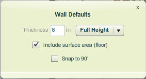
| • | Thickness field – Enter the default thickness for walls in the Thickness field. A thickness of 6 inches is set by default. |
| • | Wall Type drop-down list – Select the type of walls for which the thickness should be used by clicking on the  sign and selecting the wall type from the drop-down list. Full Height walls are selected by default. sign and selecting the wall type from the drop-down list. Full Height walls are selected by default. |
| • | Include Surface Area checkbox – When checked, floor shapes will be included automatically when you draw walls on your plan. Leave checkbox blank to draw walls without floors. This option is selected by default. |
| • | Snap to 90° checkbox – When checked, only 90° walls are created when the wall tool is used. If your plan requires angled walls, this option should be generally left unchecked. |
Note: This option affects only newly created walls. When you modify an existing wall point using the selection tool, angled walls can be made without constraint. In addition, walls will snap to 90° when dragged within a few degrees of vertical or horizontal regardless of whether this option is checked or unchecked. Selecting or de-selecting this option affects the snap to 90° setting of the surface, line and dimension tools.
| 2. | Close the Wall Defaults window by clicking on the  symbol in the top right corner of the window at the top. symbol in the top right corner of the window at the top. |
| 3. | The settings you selected will be applied to the walls that you add to your plan. |
To select surface defaults:
| 1. | Click on the Edit menu and select Surface Defaults from the menu on the right. A window will appear with the options available for the surface defaults. |
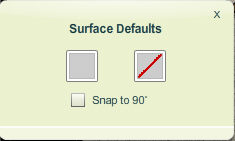
| • | Surface color – To set the default color for surfaces (floor shapes), click the gray box to the left. The gray color represents the gray default color setting for surfaces. A color palette will appear with the available colors. Select the color of your choice for the default surface color by clicking on it. Click here to learn more about selecting colors. |
Once you find the color of your choice, click on the  button at the top right corner of the color palette at the top to close it.
The color selected will be used as the default color for all new surfaces added to the plan. Individual surface colors can be changed on the plan once they have been added.
| • | Surface pattern – To set the default pattern for surfaces (floor shapes), click on the box to the right with a red line across it. The red line represents “no pattern,” which is the default surface pattern setting. A panel will appear with the available patterns. Select the default surface pattern by clicking on it. Click here to learn more about selecting patterns for a surface. |
Once you find the pattern of your choice, click on the button in the top right corner of the window to close it.
Individual surface patterns can be changed on the plan once they have been added.
| • | Snap to 90° checkbox – When checked, only 90° surface segments are created when the surface tool is used. If your plan requires angled surface segments, this option should be generally left unchecked. |
Note: this option affects only newly created surfaces. When you modify an existing surface point using the selection tool, angled surface segments can be made without constraint. In addition, surface segments will snap to 90° when dragged within a few degrees of vertical or horizontal regardless of whether this option is checked or unchecked.
| 2. | Close the Surface Defaults window by clicking on the symbol in the top right corner of the window. |
| 3. | The settings you selected will be applied to surfaces that you add to your plan. |
To select line defaults:
| 1. | Click on the Edit menu and select Line Defaults from the menu on the right. A window will appear with the options available for the line defaults. |
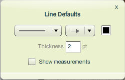
| • | Line type drop-down menu – Set the line type by clicking on the  sign to the right of the first field and select the default line type from the drop-down list. sign to the right of the first field and select the default line type from the drop-down list. |
| • | End cap style drop-down menu – Select the end cap style by clicking on the sign to the right of the second field and select the default end cap style from the drop-down list. |
| • | Line thickness field – Enter a default thickness for lines in the thickness field. The default line thickness setting is 2 points. |
| • | Line color – To set the default line color, click the black box to the far right. The black color represents the black default color setting for lines. A color palette will appear with the available colors. Select the color of your choice for the default line color by clicking on it. |
Once you find the color of your choice, click on the button in the top right corner of the window to close it.
The color selected will be used as the default color for all new lines added to the plan. Individual line color can be changed on the plan after lines have been added.
| • | Select the Show Measurements checkbox to show the line dimensions by default for all lines added to the plan. |
| 2. | Close the Line Defaults window by clicking on the symbol in the top right corner of the window. |
| 3. | Close the Line Defaults window by clicking on the symbol in the top right corner of the window. |
| 4. | The settings you selected will be applied to the lines that you add to your plan. |
To Select Dimension defaults:
| 1. | Click on the Edit menu and select Dimension Defaults from the menu on the right. A window will appear with the options available for the dimension defaults. |
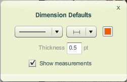
| • | Line type drop-down menu – Set the dimension line type by clicking on the sign to the right of the first field and select the default dimension line type from the drop-down list. |
| • | End cap style drop-down menu – Select the end cap style by clicking on the sign to the right of the second field and select the default end cap style from the drop-down list. |
| • | Line thickness field – Enter a default thickness for dimension lines in the thickness field. The default dimension line thickness setting is .5 points. |
| • | Line color – To set the default dimension line color, click the color box to the far right. The black color represents the black default color setting for dimension lines. A color palette will appear with the available colors. Select the color of your choice for the default dimension line color by clicking on it. |
Once you find the color of your choice, click on the button in the top right corner of the window to close it.
The color selected will be used as the default color for all new dimension lines added to the plan. Individual dimension line color can be changed on the plan after lines have been added.
Note: This setting affects only lines created with the dimension tool. Dimensions that appear on selected walls and surface segments will not be affected by these settings.
| • | Select the Show Measurements checkbox to show dimension values by default for all dimension lines added to the plan. |
| 2. | Close the Dimension Defaults window by clicking on the symbol in the top right corner of the window. |
| 3. | The settings you selected will be applied to the dimensions that you add to your plan. |
To select text defaults:
| 1. | Click on the Edit menu and select Text Defaults from the menu on the right. A window will appear with the options available for text defaults. |
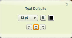
| • | Font size drop-down menu – Select the default font size by clicking on the sign to the right of the first field and selecting the font size from the drop-down list. |
| • | Bold style option – Click on the “B” button to set the default font style to bold. When bold option is selected, an orange border appears around the button. |
| • | Font color – To set the default font color, click the color box to the far right. The black color represents the black default color setting for text. A color palette will appear with the available colors. Select the color of your choice by clicking on it. |
| • | Text alignment – Set the default text alignment by clicking on the icon for align left, align center or align right appearing at the bottom of the window. |
| 2. | Close the Text Defaults window by clicking on the symbol in the top right corner of the window. |
| 3. | The settings you selected will be applied to the text that you add to your plan. |
To select photo defaults:
| 1. | Click on the Edit menu and select Photo Defaults from the menu on the right. A window will appear with the options available for photo defaults. |
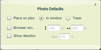
Note: Photos can appear in different forms and for different purposes from referencing items that appear in your plans to images that you can trace over. The following options allow you to establish defaults for added photos depending on the way you want them to appear.
| o | Select Place on Plan: Choose this option if you want the photo to appear on the plan itself. When you select this option, you can also select the size of the image, defined by the percentage of the original image. Click here to learn more about placing photo on the plan. |
| o | Select In window to display the image in a new window whenever someone clicks on the red picture icon. Click here to learn more about displaying the photo in a new window. |
| o | Select Trace to display a transparent version of the image. Click here to learn more about tracing an image. |
| 3. | Close the Photo Defaults window by clicking on the symbol in the top right corner of the window. |
| 4. | The settings you selected will be applied to the photos you add to your plan. |


